News
Behavior of tolerance
In mechanical drawing, the design needs to use various symbols to represent the behavior tolerance. Do you know which ones? Can you read the mechanical drawings clearly?
Geometric tolerance includes shape tolerance and position tolerance, while position tolerance includes directional tolerance and positioning tolerance. The content and tolerance representation symbol are shown in the figure below:
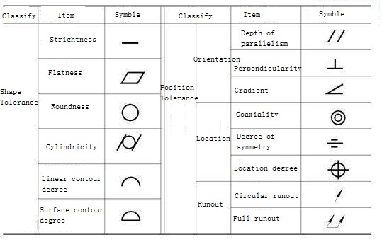
Geometric tolerance representation
The shape of tolerance
1. The straightness symbol is a short horizontal line (-), which is an index limiting the variation of the actual line to the ideal line.It is aimed at the straight line does not occur straight and the request.
2. The flatness symbol is a parallelogram, which is an index limiting the variation of the actual plane to the ideal plane.It is aimed at the demand of plane unevenness.
3. The roundness symbol is a circle (0), which is an index limiting the change of actual circle to ideal circle.It is a requirement for circular contours within a normal section (a surface perpendicular to the axis) of a part having a cylindrical surface (including a conical surface and a spherical surface).
4. The cylindrical degree symbol is a circle sandwiched between two diagonal lines (/ 0 /), which is an index limiting the change of actual cylinder to the ideal cylindrical surface.It controls various shape errors in the cross-section and axial section of the cylinder, such as roundness, plain line straightness, and axis straightness.Cylindrical degree is the comprehensive index of shape error of cylinder.
5, line profile of a symbol is a convex curve (⌒), is to limit the actual curve is an indicator of an ideal curve changes in quantity.It is required for the shape accuracy of non-circular curves.
6. The profile symbol of the surface is a semicircle above and a horizontal below, which is an index limiting the variation of the actual surface to the ideal surface. It is the requirement for the shape accuracy of the surface.
Orientation tolerance
1, parallelism (∥) is used to control the parts on the measured element (flat or straight line) relative to a benchmark elements (flat or straight line) from 0 ° in the direction of the requirements, which requires being measured elements of benchmark equidistant.
2, verticality on (an) is used to control the parts tested elements (flat or straight line) relative to a benchmark elements (flat or straight line) from 90 ° in the direction of the requirements, which requires being measured elements to reference to 90 °.
3, gradient (<) is used to control the parts on the measured elements (flat or straight line) relative to a benchmark elements (flat or straight line) in the direction of the deviation from a given Angle (0 ° ~ 90 °), which requires to reference into a certain Angle measured elements (except 90 °).
Location tolerance
1. The degree of parallelism is used to control the degree of the measured axis which should be coaxially different from the standard axis.
2. The symbol of symmetry is three horizontal lines of the middle length, which are generally used to control the degree of non-coincidence between the measured elements (center plane, center line or axis) and the basic elements (center plane, center line or axis).
3. The position symbol is a circle with two straight lines perpendicular to each other, which is used to control the variation of actual elements measured relative to their ideal position, which is determined by the standard and the correct size of the theory.
Runout tolerance
1. The circular beat symbol is the slant line of an arrow. Circular beat is the difference between the maximum and minimum reading measured by a fixed position indicator in a given direction during the unaxial movement and rotation of the measured actual elements around the datum axis.
2. The full beat symbol is the diagonal line with two arrows. The full beat is the continuous rotation of the measured actual elements around the reference axis without axial movement.

Copyright © Tianhui Machinery Co.,Ltd All Rights Reserved Website Map XML